Autocad Electrical Plc Drawing Examples
Several types of data are available to control how PLC drawings are generated with the PLC I/O utility.
The data file includes certain columns containing the information needed to generate the PLC drawings. The columns can be in any order and assigned to specific data categories when the drawings are generated. All columns are optional except the Module part number (Code) column. Three example PLC data files are found in the User folder: demoplc.xls, demoplc.csv, and demoplc_iec.xls.
The following describes the data categories that can be included in the data file.
Module Data
| Module part numbers (Code) | The code for a parametrically generated module, or a non-PLC generated symbol such as a variable speed drive. Note: The code must be found in the PLC database. |
| Address (ADDR) | The I/O address for each I/O point. This value is assigned to the "TAGA_" attribute. |
| Rack numbers (R) | The rack number of the module, used for the attribute assigned to the %%1 Prompt from the parametric data file. |
| Group numbers (G) | The group number of the module, used for the attribute assigned to the %%2 Prompt from the parametric data file. |
| Slot numbers s | The slot number of the module, used for the attribute assigned to the %%3 Prompt from the parametric data file. |
| Remote terminal panel (RTP) | The remote terminal panel ID number of the module, used for the attribute assigned to the %%4 Prompt from the parametric data file. |
| Wire numbers | The wire number used for each I/O point. |
| Module's tag | The value assigned to the TAG attribute of the module. |
| Module's Installation | The value assigned to the installation attribute of the module. |
| Module's Location | The value assigned to the location attribute of the module. |
| Description 1-5 (DESC1-DESC5) | The values assigned to the module five description attributes of the module. |
| Voltage/Input/Output (VOLTAGE) | The value used to determine whether a module is an input, output, or combination module if it cannot be determined from the parametric data file.
|
You can predefine other attributes on the module, such as Ratings, using the format:
mainvalue;attributename2=attributevalue2
For example, in the Rack column the following value:
2;RATING2=HAZARDOUS DUTY
results in a RACK value of "2" and a RATING2 value of "HAZARDOUS DUTY" on the module.
Note: Use a semi-colon between each extra attribute name and value pair.
Special PLC Values
There are some values that can be placed in a row to direct special PLC module features:
Note: There should not be any other data in the spreadsheet row.
| BREAK | Insert this keyword in the ADDRESS column of the spreadsheet where you want the PLC module to break and continue on the next ladder column. |
| SPACER | Insert this keyword in the ADDRESS column of the spreadsheet where you want to add extra space between adjacent I/O points. |
| SKIP | Insert this keyword into the CODE column right after the end of the data for the previous module where you want to skip a ladder before the next module. |
| NEW_DWG | Insert this keyword into the CODE module part number column right after the end of the data for the previous module where you want to skip to the next drawing before the next module. |
In-line Component Data
The PLC I/O Utility supports up to nine in-line components. Components for input modules are inserted left-to-right, while components for output modules are inserted right-to-left. The spacing between devices is maintained even if no component is defined for a particular column.
Repeat the columns for each in-line component. The columns of data are as follows:
| Block | The .dwg file name for the component to insert. Note: Place an asterisk (*) in front of the block name to use Insert Circuit instead of Insert Component. The other column values for this entry are annotated onto the first symbol found on the inserted circuit. |
| Tag | The value assigned to the TAG attribute of the component. For terminals, use the format TAGSTRIP:TERM. For example, a value of "TB1:25" assigns "TB1" to the TAGSTRIP attribute and "25" to the TERM01 attribute. Note: Use a colon between the TAGSTRIP value and the terminal number. |
| Description | The values assigned to the DESC attributes of the component. Use the | symbol to separate text and assign it to DESC1, DESC2, or DESC3. For example, a value of "CYCLE|START" assigns "CYCLE" to DESC1 and "START" to DESC2. |
| Location | The value assigned to the location (LOC) attribute of the component. |
| Installation | The value assigned to the installation (INST) attribute of the component. |
| Manufacturer | The value assigned to the manufacturer (MFG) attribute of the component. |
| Catalog | The value assigned to the catalog (CAT) attribute of the component. |
| Assembly | The value assigned to the assembly code (ASSYCODE) attribute of the component. |
You can predefine other attributes on the components, such as pin number assignments, using the format:
mainvalue;attributename2=attributevalue2
Enter the values in any in-line component column except the Block column.
For example, in the Location column the following value:
Field;TERM01=21;TERM02=22
results in a LOC value of "Field", a TERM01 value of "21", and a TERM02 value of "22" on the component.
Note: Use a semi-colon between each extra attribute name and value pair.
Special Wiring for In-line Components
Normally each in-line component is wired in series, connected from the bus to the I/O point, but more wiring options are also available.
Perpendicular Wire Between Adjacent Rungs
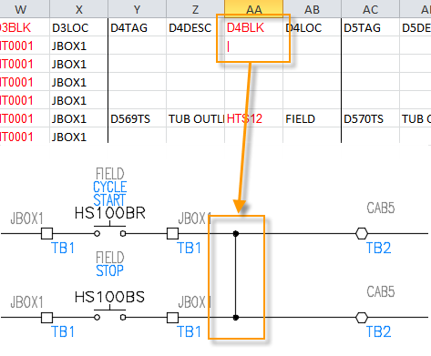
To specify a perpendicular wire connecting adjacent rungs, use the "|" character as the symbol block name for one of the available in-line devices.
Removal of Wire Connections
Follow the "|" character with four characters to control the four possible wire connections to the perpendicular wire. Use a "W" to keep the wire connection and an "X" to remove it.
- 1st character = Upper left
- 2nd character = Upper right
- 3rd character = Lower left
- 4th character = Lower right
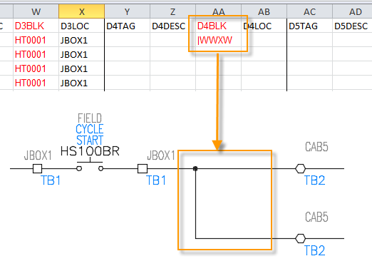
For example, a block name of "|WWXW" inserts a perpendicular wire and trims the lower left wire connection.
Loop Back Around
You can also loop back instead of going all the way across to a power bus. To loop back to the right, insert "|XWXW" as the first in-line device.

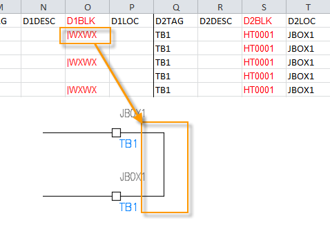
To loop back to the left, use "|WXWX".
Source: https://knowledge.autodesk.com/support/autocad-electrical/learn-explore/caas/CloudHelp/cloudhelp/2022/ENU/AutoCAD-Electrical/files/GUID-36DC8A4E-BB2A-48D5-8E98-473F964108EB-htm.html
0 Response to "Autocad Electrical Plc Drawing Examples"
Post a Comment